| Site Map | Polytopes | Dynkin Diagrams | Vertex Figures, etc. | Incidence Matrices | Index |
When dealing with sets of polytopes and esp. therefrom derived further polytopes, then some notions are useful. J. Bowers once introduced the army concept:
Esp. the army general also is known as the convex hull. The regiment colonel then could be considered as the locally convex hull, i.e. using the convex hull of each vertex figure.
This concept e.g. is being used for vertex regulars. Or is being used for facetings, when considering some given dimensional embedding space. – Shortly thereafter W. Krieger brought up the dual concept. While the first was based on military terms of land forces, the second similarily got based on navy terms.
Esp. the fleet admiral also is known as the intersection kernel, somtimes also just called the core.
That concept intentionally was designed for the dual process of faceting, the stellation.
But when considering facetings, there are occasions, where the navy concept proves suitable too. E.g. the sets of uniform polytopes of D-dimensional space each can be grouped into classes of figures with the same ridge (i.e. their D-2-dimensional elements) skeletons. In the above terms those would be members of the same ship. For each class one representative (i.e. its comodore) can be chosen as the most convex one possible. Each such class then can be investigated further for other polytopes with uniform facets only, following the constraint that the ridges remain a non-empty subset of the skeleton under consideration. – For D=3 this investigation was subject of the article Axial-Symmetrical Edge-Facetings of Uniform Polyhedra of the author in 2002. The then being found polyhedra will be detailed below. So far that work of the author had been for display only on this site, hosted by U. Mikloweit.

So the process of investigation can be outlined as the following:
Within the cited article and within most of the below linked sub-pages the mentioned further constraint was being chosen to get polyhedra which provide at least an n-gonal axial rotation symmetry, where n > 2. The article moreover provides an algorhythm on how to process the above steps in an automated way and even discusses its efficiency.
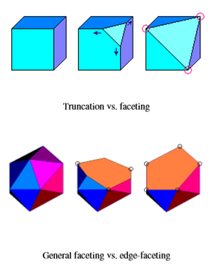
Before going ahead, we first have to get more explicit on the used terms. A truncation in general chops off some vertex of a given polytope (or does so in a globally symmetrical manner all over at all vertices at the same time) and replaces that very vertex by some sectioning facet underneath. That one happens to be an instance of the corresponding vertex figure. The depth of truncation as such in general remains undefined, if no further restrictions are being considered (such as resulting in a further uniform polytope, i.e. especially one with equally sized edges only). But, even more general, also the tilt of that intersecting hyperplane needs not to be understood as orthogonal to the vertex ray. Now, if the depth and tilt of a truncation is being chosen such that the cutting hyperplane runs through at least some of the vertices of the polytope (that count surely has to be large enough to define the cutting hyperplane uniquely), then this special instance of truncation is called a faceting. If a faceting plane of a polyhedron cuts within edges only, then it is called an edge-faceting. More generally, if a faceting hyperplane of a polytope cuts within ridges only, then it is called a ridge-faceting. Note that every ridge-faceting of a uniform polytope always will be orbiform itself at least.
As it is obvious, not all polytopes ensure that the set F(S) is indeed larger than the facet set of the comodore itself. For uniform polyhedra this surplus requires at least that the vertex figure is non-trigonal. But furthermore, some non-next turning edge-circuit has to exist, which happens to be planar. The uniform polyhedra, which pass both requirements, are given in the following table, grouped by their according ship (here equivalent to: their regiment). Their most convex representant each, i.e. their comodore (here equivalent to: their colonel) is presented on the lefthand side together with the naming codes. These thus give a clue on the possible facet types of that ship. Both furthermore link onto the respective subpage, which then enlists all the possible ridge-facetings. The individual ridge-facetings, as already seen in the central column, then provide instead of those #{p} bits the according counts each (optionally followed by some suffix to distinguish different cases with the same counts).
The picture triples in the central column of the following table (and within all the subpages) for axial polyhedra always provide a top-, a side-, and a bottom-view. For full symmetrical polyhedra those provide a view onto the different symmetry axes each.
|
Comodore of Ship (linking to subpage) | Example of Ridge-Faceting | Counts & Symmetries |
Contained Uniform Polytopes *) already uses a sub-skeleton only |
|---|---|---|---|
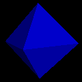 oct-#{3}-#{4} |
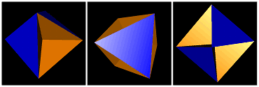 oct-4-3 |
| |
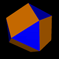 co-#{3}-#{4}-#{6} |
 co-8-0-4 |
| |
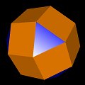 sirco-#{3}-#{4}-#{8} |
 sirco-4-9-5-a |
| |
 gocco-#{8/3}-#{3}-#{4} |
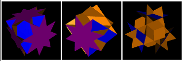 gocco-3-4-9-a |
| |
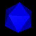 ike-#{3}-#{5} |
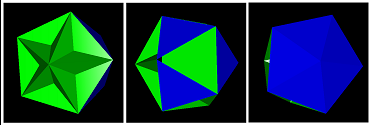 ike-10-6 |
| |
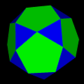 id-#{3}-#{5}-#{10} |
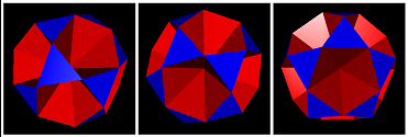 id-20-0-6 |
| |
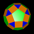 srid-#{3}-#{4}-#{5}-#{10} |
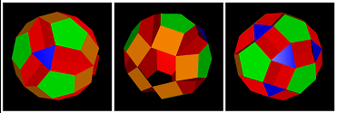 srid-5-15-9-9 |
| |
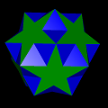 sidtid-#{5/2}-#{3}-#{4}-#{5} |
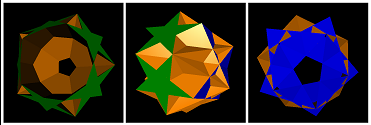 sidtid-5-5-15-0-b |
| |
 siid-#{5/2}-#{3}-#{6}-#{10} |
 siid-6-10-10-6-d |
| |
 sissid-#{5/2}-#{3} |
 sissid-6-10 |
| |
 did-#{5/2}-#{5}-#{6} |
 did-6-6-7 |
| |
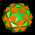 raded-#{5/2}-#{4}-#{5}-#{6} |
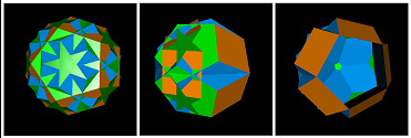 raded-6-10-6-10-a |
| |
 gidditdid-#{3}-#{10/3}-#{5}-#{6} |
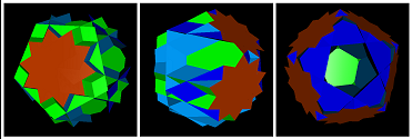 gidditdid-10-6-6-10-a |
| |
 gid-#{5/2}-#{3}-#{10/3} |
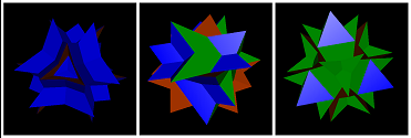 gid-6-10-3-a |
| |
 gaddid-#{5/2}-#{3}-#{10/3}-#{4} |
 gaddid-1-5-11-25 |
| |
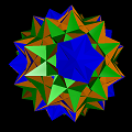 gidrid-#{5/2}-#{3}-#{4} |
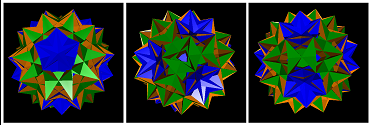 gidrid-24-40-60 |
|
© 2004-2026 | top of page |