The root lattice C4 is provided by the vertex set of test.
Both the Voronoi complex and the Delone complex of C4 are (mutually shifted copies of) test.
(This is why both Klotz construction devices here result in the same tiling.)
©
©
links

| Name | Ammann Beenker tiling |
| Projection device |
TC4 = T*C4 The root lattice C4 is provided by the vertex set of test. Both the Voronoi complex and the Delone complex of C4 are (mutually shifted copies of) test. (This is why both Klotz construction devices here result in the same tiling.) |
| |
|
External links |
|
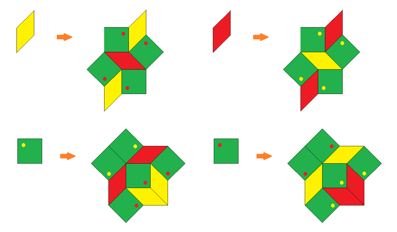
The right picture shows not only an overlay of the second iteration of the below provided substitution rule – as being easily achieved in a local way by just selecting the vertex configurations of type 6 (cf. also the relation of the respective acceptance regions) – but also provides a consistent 2-coloring of the rhombs, as found in this article: For that purpose first the vertices would have to be colored alternatingly, and then the rhombs would get the color of their acute angles.
As can be seen in this picture too, this coloring not only is consistent wrt. to the 2nd iteration of the substitution (as displayed in the picture), but already to its 1st iteration (outlined below). For that purpose the distinction of the rhomb types would ask for a corresponding coloring of the already being used orientation mark, thus then effectively resulting in a 4 tile substitution rule. – That mentioned consistency clearly could also be understood from the projection method. The alternation rule of vertex coloring of the tiling lifts back to an alternation of lattice points of embedding space, at least those of the being projected acceptance domain. There that alternation amounts just in the 2 alternate sublattices of odd resp. even coordinate sums, and therefore even can be continued beyond that domain as well.
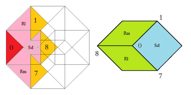
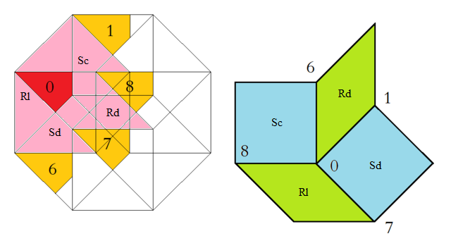
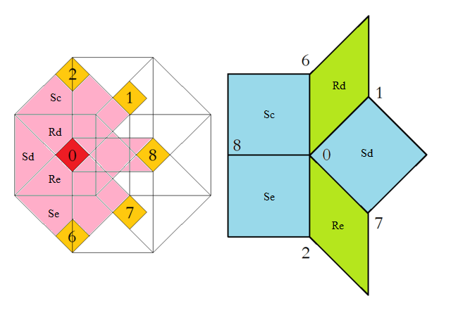
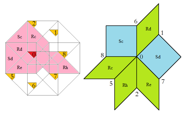
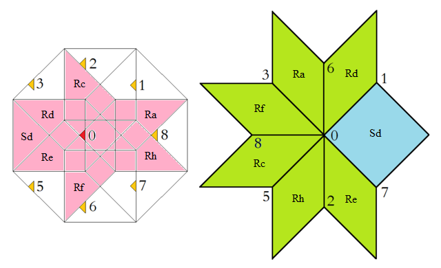
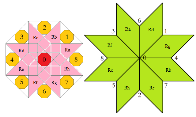
At the left the octagonal acceptance domain, which corresponds to the projection of a single Voronoi cell, which here is a tes into the perp space. At the right the corresponding vertex configurations of the tiling space are shown. There the incident tiles are projections of the polygonal faces of the Delone cell, which here is a tes as well. Accordingly the tiles all are tetragons, within the chosen projection either squares or (45°,135°)-rhombs. Within the following table the different regions of the acceptance domain are marked in red (and additionally labeled as "0"), which 1 by 1 correspond to the shown vertex configuration each.
When lifting the incident tiles of tiling space back into embedding space, and selecting the dual Voronoi cell boundary of that specific Delone cell boundary, the corresponding projection shadow into perp space always is shown there in rose. These acceptance domains of tiles also are labeled accordingly by "S_" (for squares) resp. "R_" (for rhombs). Obviously the red regions are just the common intersections each of those rosaic tile domains. Btw., the prism products of alike marked regions of tiling space (tiles) and of perp space (their acceptance domains) happens to be the corresponding Klotz.
Finally the relative edge shifts likewise are lifted back into perp space (shown in yellow and labeled with mere numbers). Therefrom then the exact incident next vertex configuration could be deduced, provided that the exact relative perp space coordinate of the starting "0" vertex is given. – In fact, these tilings all happen to belong to a single local isomorphism class, the specific representant can be coded by that starting perp space coordinate c⊥. Thereby then the full infinite tiling is defined completely.
 Type 1 relative frequency = [sqrt(2)-1]/8 = 5.177670 % count of orientations = 8 |
 Type 2 relative frequency = [3-2 sqrt(2)]/4 = 4.289322 % count of orientations = 8 |
 Type 3 relative frequency = [5 sqrt(2)-7]/4 = 1.776695 % count of orientations = 8 |
 Type 4 relative frequency = [17-12 sqrt(2)]/4 = 0.735931 % count of orientations = 8 |
 Type 5 relative frequency = [29 sqrt(2)-41]/8 = 0.152416 % count of orientations = 8 |
 Type 6 relative frequency = 17-12 sqrt(2) = 2.943725 % count of orientations = 1 |
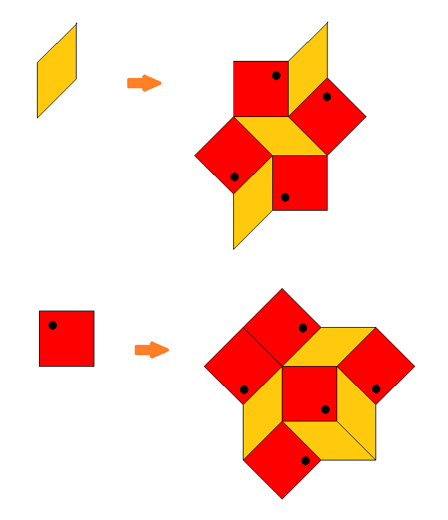
The Ammann-Beenker tiling alternatively can be obtained by an iterated application of a substitution rule, which requires an additional orientation of the squares (black dots). – From the above projection device it is evident, that the acceptance domains of vertex incident (para-space) squares are just those large outer overlapping (perp-space) squares shown within the acceptance domain. The acceptance domain of the to be marked vertex of the (para-space) square then is exactly the (perp-space) region of type 1. This observation in turn not only shows that any square of this tiling has exactly one incident vertex configuration of type 1, but conversely that this here required decoration mark can be derived from the square surrounding in a local way within any (undecorated) infinite tiling!
The (linear) scaling factor of patch inflation then is evidently ϑ = 1+sqrt(2) = 2.414214. Note that several squares reach beyond the (scaled) original outline, and thus would contribute to the below provided substitution matrix only by one half each.
Substitution matrices:
uncolored:

rhombs  | 3  2
squares | 4  3


2-colored:

yellow rhombs         | 2  1  0  2
red rhombs            | 1  2  2  0
squares marked yellow | 2  2  1  2
squares marked red    | 2  2  2  1
© 2004-2026 | top of page |